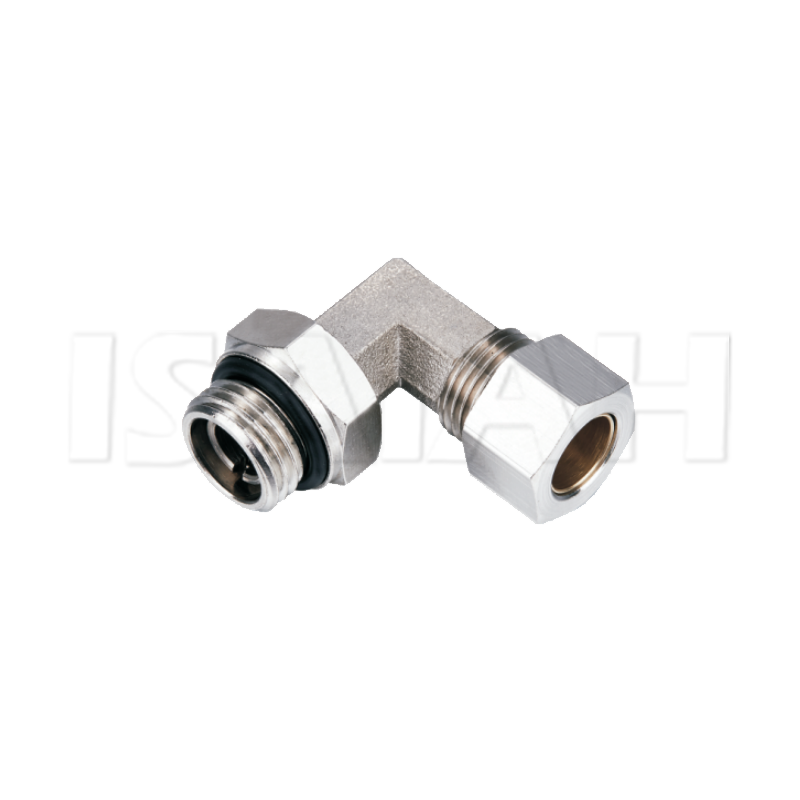
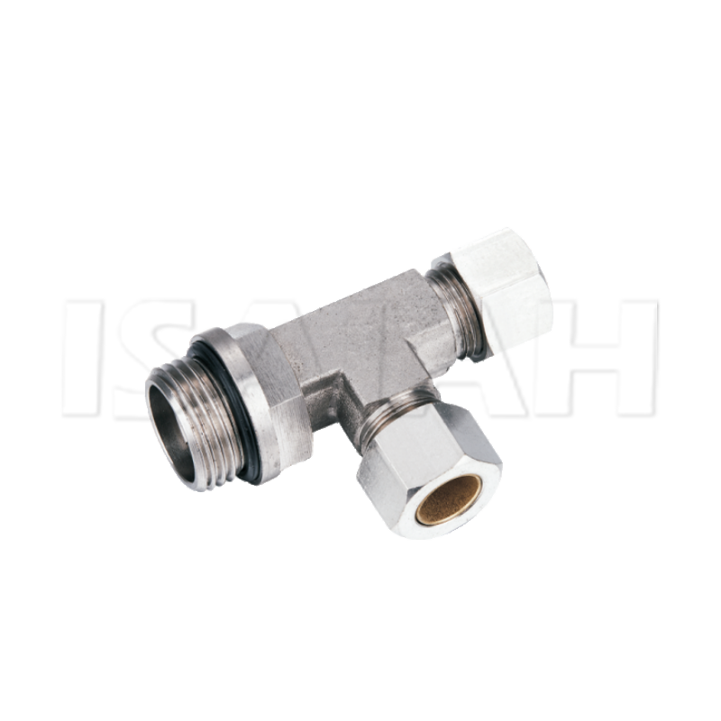
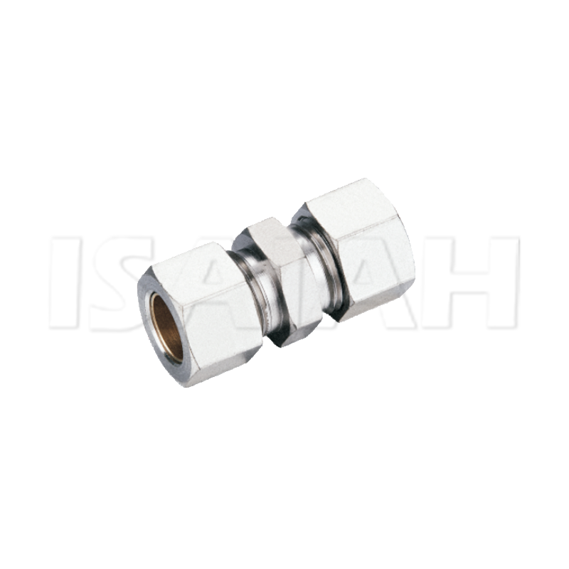
Unplanned downtime destroys operational margins across industrial facilities. Wasted compressor energy drives up overhead costs significantly. Pneumatic leaks directly cause both of these severe issues. Quick-disconnect systems offer undeniable speed during initial assembly. However, they often fail prematurely in critical or high-stress setups. High-vibration environments demand superior mechanical grip. They require the reliable seal of properly specified compression fittings.
We will explore a technical, decision-stage framework for evaluating these components. You will learn how to shortlist the exact parts you need. We base this evaluation on system pressure, ambient environment, and material constraints. This guide provides actionable steps to upgrade your pneumatic connections. You will eliminate persistent air leaks and improve overall machine reliability. Selecting the correct hardware transforms a vulnerable air system into a resilient power network.
Key Takeaways
Material alignment is critical: Tubing and fitting materials must match to prevent galvanic corrosion and thermal expansion disparities.
Ferrule design dictates performance: Single-ferrule designs suit standard applications, while double-ferrule systems are required for severe vibration or pressure pulsation.
Preparation prevents failure: Over 70% of compression fitting leaks stem from improper tube preparation (poor cuts, lack of deburring) rather than component defects.
Thread specification matters: Selecting the correct threaded compression fittings prevents thread galling and ensures compliance with regional standards (NPT vs. BSPT).
Evaluating Compression Fittings vs. Push-to-Connect Systems
Engineers must define clear success criteria when designing pneumatic circuits. You must determine if a connection requires a permanent mechanical seal. Sometimes, a semi-permanent seal works best. Other nodes require frequent disconnection for maintenance. Understanding these operational realities dictates your component choices.
Push-to-connect systems dominate lightweight automation. They allow faster initial rollout. Installers simply push the tubing into the port. However, they rely entirely on internal O-rings to maintain the air boundary. These elastomer O-rings possess distinct vulnerabilities. They remain highly susceptible to side-load leakage. If a hose pulls at an angle, the O-ring compresses unevenly. Air quickly escapes through the resulting gap. Furthermore, airborne chemicals and harsh washdown fluids degrade these internal elastomers over time.
Compression setups present a different operational reality. They require slower installation. Technicians must use wrenches and adhere to specific torque procedures. However, this process creates a robust metal-to-metal seal. You can also create a metal-to-plastic seal using specific inserts. This mechanical bond resists heavy vibration seamlessly. It withstands significantly higher pressure thresholds than standard O-ring designs.
We must operate under a transparent assumption regarding system deployment. Compression systems carry a higher initial labor cost for installation. Technicians spend more time preparing tubes and tightening nuts. Despite this initial hurdle, they yield significantly fewer maintenance intervals. In high-stress industrial environments, this mechanical stability prevents catastrophic air loss. It safeguards critical automated processes from sudden pressure drops.
Understanding the mechanical physics of a joint prevents field errors. Every technician should know how these parts interact. Standard compression tube fittings utilize three primary components. Each plays a distinct role in securing the pneumatic media.
The Body: This central component provides the precise seating angle. It contains the primary flow path for the compressed air. The body features external threads that engage the nut.
The Nut: This component acts as the force delivery mechanism. It transfers applied rotational torque into linear mechanical compression.
The Ferrule(s): This represents the critical sealing element. The ferrule actually bites into the outer wall of the tubing. It bridges the gap between the nut and the body.
We call the physics of this connection the swaging process. When you tighten the nut, it pushes the ferrule forward. The ferrule encounters the tapered internal geometry of the fitting body. Because the body acts as a ramp, it forces the ferrule inward. The ferrule then wedges tightly against the tubing wall.
This localized deformation creates two distinct advantages. First, it establishes a primary fluid seal. Air cannot escape past the ferrule's forward edge. Second, it generates structural grip. The bite prevents the tube from blowing out under high pneumatic pressure. The ferrule essentially becomes a permanent part of the tubing once fully swaged. The perfection of this bite depends entirely on component alignment and material hardness.
Decision Matrix: Single-Ferrule vs. Double-Ferrule Designs
Choosing between single and double-ferrule geometries impacts system longevity. Each design serves distinct industrial applications. You must evaluate vibration profiles before selecting a specific type.
Single-Ferrule Fittings
Single-ferrule designs represent the industry standard for general pneumatics. The mechanism is straightforward. As you tighten the nut, the nose of the ferrule bites into the tube. Simultaneously, the back of the ferrule bows outward slightly to grip the tubing wall. This bowing action provides the holding power.
We recommend this use case as a cost-effective solution. They work perfectly for standard pneumatic systems experiencing minimal vibration. Think of static air lines inside a control cabinet. However, single ferrules possess a mechanical limitation. The installation torque transfers directly from the nut to the single ferrule. This friction can occasionally cause tube rotation during installation. If the tube twists excessively, it introduces stress into the pneumatic circuit before operation even begins.
Double-Ferrule Fittings
Heavy industries demand more sophisticated mechanical solutions. Double-ferrule setups separate the sealing function from the gripping function. The front ferrule handles the primary sealing duties. It wedges securely into the body. The back ferrule handles the gripping function. It rolls inward to bite the tube firmly.
This design dominates high-vibration environments. We see them heavily utilized in critical instrumentation and heavy-duty industrial pneumatics. The mechanical advantage is substantial. They remain highly resistant to vibration fatigue. The back ferrule acts as a shock absorber. It isolates harmonic vibrations before they reach the primary seal. Additionally, installation torque is not transferred as rotational force to the tubing. The back ferrule rotates independently, keeping the tube perfectly stationary during final tightening.
Performance Comparison Matrix
Design Type | Vibration Resistance | Primary Function | Cost Profile | Risk of Tube Twist |
Single-Ferrule | Moderate | Combined Seal and Grip | Economical | Higher |
Double-Ferrule | Excellent | Separated Seal and Grip | Premium | Minimal |
Material Compatibility and Specifying Threaded Compression Fittings
Selecting the wrong material guarantees catastrophic system failure. You cannot mix materials blindly. The hardness relationship between the tubing and the fitting dictates the success of the seal.
The fitting ferrule must always be harder than the tubing material. If the tubing is harder, the ferrule simply flattens out. It will fail to secure a proper bite. For example, you must use stainless steel fittings on stainless steel tubing. Conversely, you can use brass fittings on softer copper or nylon tubing. Brass provides enough hardness to swage into copper without shattering. Galvanic corrosion also poses a serious threat. Using dissimilar metals in humid environments creates a battery effect. One metal acts as an anode and corrodes rapidly. Always match metallurgy whenever possible.
Managing plastics requires specialized techniques. Many pneumatic circuits utilize soft polyurethane or nylon tubing. When using metallic compression components on soft pneumatic tubing, metallic tube inserts are strictly required. Installers call these components stiffeners. You press the stiffener into the inner diameter of the plastic tube. This prevents the tube wall from collapsing inward when the ferrule compresses. Without a stiffener, the plastic simply yields. The connection will blow apart under pressurized loads.
You must also master thread standards for proper system integration. Upgrading equipment often requires connecting to existing threaded ports. You must evaluate regional standard requirements before purchasing parts. North American facilities heavily rely on NPT (National Pipe Tapered) threads. European and Asian facilities typically specify BSPT (British Standard Pipe Tapered) or BSPP (Parallel) threads. NPT and BSPT look identical to the naked eye. However, their thread angles differ entirely. Forcing an NPT fitting into a BSPT port destroys the threads and guarantees an air leak.
Properly specifying threaded compression fittings requires understanding sealants. Tapered threads require gap-filling assistance. Define the necessity of thread sealants early in your maintenance protocols. You should apply high-quality PTFE tape or liquid pipe sealants. These compounds fill the microscopic spiral leak paths between the male and female thread crests. Apply tape smoothly in the direction of the threads. Leave the first thread bare to prevent tape shreds from entering the pneumatic stream.
Implementation Risks and Installation Best Practices
Premium components fail without proper assembly techniques. Human error accounts for the vast majority of pneumatic system issues. We must systematically mitigate these risks on the factory floor.
Mitigating Human Error
Over 70% of compression fitting leaks stem directly from improper tube preparation. They rarely result from actual component defects. Maintenance teams must treat tube preparation as a critical science.
Square Cuts: Tube cuts must be exactly square. You must achieve a 90-degree angle relative to the tube axis. Hacksaws tear the metal and create jagged angles. Always use a dedicated, sharp tube cutter.
Deburring: You must remove all burrs from the inside and outside edges. Micro-scratches from failure to deburr will cause immediate leak paths. The ferrule cannot seal against a scratched surface.
Bottoming Out: The tube must rest firmly against the shoulder of the fitting body before tightening. If you stop short, you create a dead volume space inside the fitting. This alters fluid dynamics and weakens the grip.
Torque and Overtightening Realities
Novice mechanics often assume tighter is better. This assumption destroys pneumatic systems. More torque does not equal a better seal. Overtightening crushes the tubing aggressively. It compresses the inner diameter and compromises the internal bore. This heavily restricts pneumatic flow, starving downline cylinders of required air volume.
You must establish standardized turns-from-finger-tight (TFFT) metrics for your maintenance teams. Finger-tight means the nut is tightened strictly by hand until resistance is felt. No tools are used yet. From that exact position, technicians apply a wrench. The industry standard typically dictates 1-1/4 turns for standard sizes (like 1/4-inch to 1-inch tubing). However, you must always defer to the specific manufacturer spec. Using a permanent marker to draw a line on the nut and body helps track exact rotational progress.
Addressing Thread Galling
Stainless steel applications introduce a unique metallurgical risk. Cold welding, commonly known as thread galling, can occur during installation. As stainless threads rub together under extreme pressure, the protective oxide layer scrapes off. The raw metals touch and fuse together instantly. The nut locks up permanently. You can neither tighten nor loosen it.
Outline a strict requirement for specific anti-seize lubricants on nut threads. A tiny drop of silver-grade or nickel-based anti-seize prevents this fusion. Apply it only to the rear threads of the fitting body. Never allow anti-seize to touch the ferrule or enter the pneumatic air stream. Proper lubrication ensures smooth torque transfer. It allows the ferrule to swage cleanly without the nut freezing prematurely.
Conclusion
Fixing pneumatic leaks requires a strategic approach to component selection. Base your final procurement logic on three distinct pillars. First, verify the maximum system pressure to ensure mechanical safety limits. Second, assess environmental conditions, specifically focusing on ambient vibration and external corrosion risks. Third, confirm media compatibility between the tubing, the internal fluids, and the fitting materials.
Take immediate next-step actions to fortify your facility. Audit your current pneumatic failure rates across all machine nodes. Look for patterns. If push-to-connect O-rings are routinely failing due to side-loading or unexpected pressure spikes, act immediately. Transition those specific vulnerable nodes to double-ferrule compression systems. Finally, always request material test reports (MTRs) from your vendors for highly critical applications. Certified materials guarantee the exact hardness and chemical resistance required for long-term reliability.
FAQ
Q: Can you reuse compression fittings?
A: The fitting body and nut can generally be reused safely. However, the ferrule permanently deforms and swages onto the tubing during the initial installation. It becomes a fixed part of that tube. If you disassemble the connection, you must use a new tube end and new ferrules to guarantee a leak-free seal upon reassembly.
Q: Do compression fittings work on plastic pneumatic tubing?
A: Yes, they work extremely well. However, the plastic tubing must be strictly compatible with your system's maximum pressure. Additionally, you must install a rigid metallic tube insert (stiffener). This insert supports the inner diameter of the plastic. It prevents the tube from collapsing inward against the ferrule's heavy compressive force.
Q: What is the difference between a flare fitting and a compression fitting?
A: Flare fittings require specialized mechanical tools to physically expand and shape the end of the tubing outward before assembly. Compression fittings require absolutely no special tube flaring tools. They rely entirely on the internal ferrule physically biting into a standard, straight-cut piece of tubing as you tighten the nut.