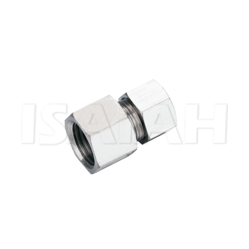
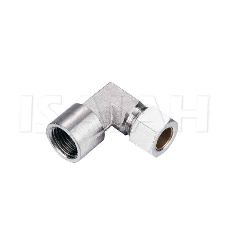
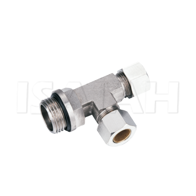
Compressed air remains one of the most expensive utility resources in modern industrial manufacturing environments. Even minor system leaks directly impact operational overhead. They severely shorten the lifespan of central compressors. Facility managers must secure pneumatic lines to avoid catastrophic pressure drops. While push-to-connect and standard threaded pipe options exist, engineers frequently specify robust mechanical alternatives. They rely on brass compression fittings for semi-permanent pneumatic layouts. These critical applications require strict structural rigidity. They also demand high vibration resistance over thousands of cyclical machine actuations. Relying on inferior connection methods invites mechanical failure on the factory floor.
This guide examines the essential mechanical, material, and operational criteria required for a reliable layout. You will learn how to evaluate and integrate these durable components into complex industrial pneumatic systems. We cover tubing compatibility constraints, critical miniaturization tactics, and precise installation protocols. You will discover actionable strategies to prevent premature joint failure entirely.
Key Takeaways
Mechanical Integrity: Brass compression fittings utilize a ferrule-driven mechanical grip that resists pneumatic vibration and thermal cycling better than standard push-to-connect alternatives.
Material Pragmatism: Brass offers a highly cost-effective balance of corrosion resistance, durability, and malleability compared to plastics or rigid stainless steel.
Plastic Tubing Compatibility: Safe deployment with polymer pneumatic lines requires internal tube supports (inserts) to prevent wall collapse under compression.
Installation Sensitivity: The primary cause of joint failure is improper installation—specifically, over-tightening that distorts the ferrule or uneven tube cutting.
The True Cost of Pneumatic Leaks and System Vibrations
Unplanned pressure drops wreak havoc on production lines. Pneumatic actuators require consistent air volume to function correctly. When system pressure fluctuates, cylinder speeds become highly inconsistent. Actuators fail to reach full stroke limits. Machine timing falls out of sync. This causes manufacturing defects and unacceptable scrap rates. Furthermore, main line compressors must work overtime to compensate for escaping air. They continuously draw excess electricity. This electrical waste inflates monthly utility bills substantially.
Industrial pneumatics operate in harsh, dynamic environments. They face continuous micro-vibrations daily. Cyclical valving fires repeatedly. Stamping presses shake the structural framework. Heavy machinery transfers kinetic energy directly into rigid piping. Over time, these relentless micro-vibrations act upon standard threaded joints. They gradually back out threaded connections. The loosening joint creates a slow, invisible air leak.
Engineers define strict success criteria for pneumatic layouts. A successful network requires components that deliver a verifiable mechanical seal. Assembly technicians must build this seal without performing hot work. Welding presents severe safety hazards in active manufacturing zones. Plant managers strictly prohibit open flames. Additionally, installers should avoid specialized, heavy crimping tools. Plant maintenance teams need scalable, easily serviceable connection strategies.
The Mechanics of the Seal: Why Compression Fittings Excel
The core advantage lies in a simple, three-part component architecture. A standard assembly features a main body, a threaded nut, and a sealing ring known as a ferrule or olive. You slide the nut and ferrule onto the tubing. You insert the tubing directly into the fitting body. As you tighten the nut, it generates immense axial force. This force drives the ferrule forward into a tapered seat inside the body. The taper forces the ferrule to compress inward. It bites aggressively into the outer wall of the tubing. This deep mechanical bite seals the internal pressure perfectly.
Engineers highly value compression fittings for their unique vibration dampening properties. Rigid threaded pipes transfer vibration straight into the joint threads. This causes rapid metal fatigue. Eventually, the pipe snaps off at the root thread. The ferrule solves this critical issue. It acts as a dedicated mechanical dampener. It physically isolates the flexible tube from the rigid metal body. Kinetic energy dissipates across the ferrule rather than concentrating at a single stress riser. This mechanism prevents catastrophic fatigue failure.
You must understand the exact constraints of component reusability. The main fitting body and the outer nut remain fully reusable across multiple maintenance cycles. However, the internal ferrule deforms permanently during the initial tightening process. It swages tightly onto the tube exterior. You cannot slide it off. If you must disassemble a connection, you cannot simply re-tighten the old ferrule. Reassembly requires you to cut off the deformed tube end entirely. You must discard the old ferrule. You must install a brand-new ferrule to guarantee absolute seal integrity.
Evaluating Brass Against Alternative Fitting Materials
Brass provides exceptional resistance to mechanical shock compared to standard plastics. Many entry-level systems utilize plastic push-to-connect modules. Plastics degrade rapidly under prolonged ultraviolet light exposure. Welding arcs and overhead skylights emit heavy UV radiation. The polymer embrittles over time. A stray wrench blow during routine machine maintenance easily shatters a brittle plastic joint. This results in an immediate pneumatic blowout. Brass effortlessly absorbs incidental physical impact on the busy factory floor.
We must also evaluate brass against rigid stainless steel alternatives. Stainless steel offers extreme hardness. However, this extreme hardness creates installation challenges. Mechanics must apply massive torque to swage a stainless ferrule properly. Incorrect torque causes thread galling. Brass is significantly softer. It allows the internal ferrule to swage smoothly. Installers can easily compress it onto softer copper lines or rigid nylon tubing. Stainless steel carries a prohibitive procurement cost. Conversely, brass is highly economical. It handles standard shop air pressures ranging from 90 to 150 PSI flawlessly.
Corrosion considerations heavily influence material selection. Compressed air inherently carries residual moisture. Central air dryers occasionally fail or underperform. Condensation builds up inside the piping network. Uncoated steel components rust from the inside out. Rust flakes travel downstream and destroy sensitive pneumatic valves. Brass possesses robust natural resistance to internal moisture. It will not introduce rust particulate into the air stream. However, you should note specific limitations. Brass degrades in highly acidic environments. Do not specify brass for specialized chemical washdown zones commonly found in poultry processing facilities.
Material Comparison Matrix
Material Type | Vibration Resistance | Impact Tolerance | Relative Cost | Ideal PSI Range |
Standard Plastic | Low to Moderate | Very Low | Inexpensive | Up to 120 PSI |
Brass | High | High | Moderate | 90 - 250 PSI |
Stainless Steel | Very High | Very High | Expensive | Up to 10,000 PSI |
Implementation Rules: Tubing Compatibility and Miniaturization
Modern automated machinery relies extensively on flexible polymer tubing. Polyurethane, nylon, and polyethylene lines route air easily around moving robotic axes. However, mating rigid metal fittings with soft plastic presents a distinct physical challenge. When the brass ferrule compresses inward, it applies tremendous crushing force. Hollow plastic tubing lacks internal structural rigidity. The tube wall simply collapses inward under this mechanical pressure. The connection slips out entirely.
You must mitigate this collapse risk. Safe deployment mandates the strict use of internal brass inserts. You press these small cylindrical supports directly into the open end of the plastic tube before assembly. The insert serves as an unyielding internal anvil. When the external ferrule tightens, it sandwiches the polymer wall against the rigid insert. This traps the tubing securely. It prevents wall collapse entirely.
Engineers must carefully evaluate tube wall thickness limits prior to procurement. Extremely thin-walled polyethylene tubing often lacks the physical mass required to withstand aggressive ferrule compression. The metal edge simply slices through the thin plastic layer. Always verify exact dimensional specifications. Match your tubing outside diameter (OD) and inside diameter (ID) to manufacturer data sheets precisely.
Deploying Mini Compression Fittings
Complex automated equipment demands extreme spatial efficiency. Engineers constantly struggle with space-constrained layouts. Modern valve manifolds pack dozens of control solenoids into incredibly tight clusters. Small robotic end-effectors require internal air routing through narrow mechanical wrists. Standard hex nuts require significant clearance space. Technicians simply cannot maneuver a standard wrench inside these dense assemblies.
In these challenging scenarios, you should specify mini compression fittings. Manufacturers engineer these specialized variants with a significantly reduced external footprint. They utilize smaller hex profiles and shorter body lengths. They fit easily inside cramped electrical control panels. They allow technicians to assemble dense pneumatic manifolds without overlapping wrench interference.
Miniaturization directly impacts system flow rates. Smaller external dimensions require a narrower internal diameter. This internal restriction affects your downstream cubic feet per minute (CFM) output. If you restrict CFM too severely, downstream pneumatic cylinders will actuate sluggishly. They might fail to generate the necessary clamping force. Always calculate flow rate requirements meticulously. Ensure the restricted internal diameter still delivers adequate air volume to satisfy the peak demands of the actuator.
Installation Risks and Procurement Logic
Even premium materials fail if installed incorrectly. Field technicians frequently cause premature system failure through careless assembly techniques. Industrial maintenance forums constantly highlight one specific error. Installers chronically over-tighten the connection nut.
Applying excessive torque creates disastrous results. Over-tightening crushes the brass ferrule entirely out of shape. The deformed metal shears straight through the tubing wall. This creates hidden micro-cracks in the line. The line inevitably blows out under peak surge pressure. You must enforce strict, standardized tightening protocols across your maintenance team.
Follow these established assembly procedures to ensure reliability:
Cut the tube perfectly square: Use a specialized tubing cutter. Never use hacksaws or utility knives. Uneven cuts prevent the tube from seating flat against the internal body shoulder.
Remove all internal and external burrs: Metal shavings damage the sealing surfaces. Clear all debris prior to assembly.
Seat the components manually: Push the tube fully into the fitting body until it bottoms out against the internal shoulder.
Tighten finger-tight: Thread the nut downward by hand until it stops naturally. Ensure you do not cross-thread the fitting.
Apply precise wrench turns: Use a wrench to tighten the nut a specified number of turns. For standard metal lines, manufacturers typically recommend one and one-quarter (1-1/4) turns past finger-tight. For plastic lines utilizing inserts, the requirement often shifts. Always consult the specific manufacturer catalog.
Procurement departments require strict shortlisting criteria to avoid costly purchasing mistakes. Ordering incompatible components delays machine commissioning schedules for weeks. Apply rigorous logic when sourcing parts.
Verify Thread Standards: Check the port threads on your pneumatic cylinders. Identify whether they use National Pipe Taper (NPT) or British Standard Pipe Taper (BSPT). Mating NPT threads into BSPT ports guarantees a massive air leak. The thread angles differ significantly. They will strip each other during installation.
Match Maximum Pressure Ratings: Never select components based solely on nominal operating pressure. A system running at 100 PSI experiences violent transient pressure spikes when large valves suddenly slam shut. These surges easily exceed 200 PSI momentarily. You must specify components rated to handle the absolute maximum transient surge your layout generates.
Standardize Configurations: Limit the variety of shapes in your inventory. Stock standard straights, 90-degree elbows, and run tees. Avoid overly complex multi-branch configurations if standard tees suffice. This simplifies inventory management.
Conclusion
Brass compression assemblies remain an absolute staple in industrial pneumatics. They deliver superior vibration dampening properties compared to rigid threaded pipes. They offer far greater physical impact resistance than standard plastic alternatives. They represent a highly reliable, mechanically sound bridge. This bridge seamlessly connects rigid factory infrastructure with flexible, fast-moving machine operations.
Plant engineers should proactively audit their current pneumatic systems. Identify zones experiencing repeated push-to-connect blowouts. Standardize your tubing materials across the facility to simplify inventory constraints. Consult manufacturer sizing matrices carefully. Select the precise component geometries and internal inserts required for your specific polymer lines. Implementing these robust, proven connectors will drastically reduce unplanned air leaks, stabilize machine performance, and ultimately lower your monthly utility expenditures.
FAQ
Q: Can you use brass compression fittings on plastic pneumatic tubing?
A: Yes, provided an internal tube support (insert) is used. The insert pushes inside the open end of the polymer tube. It maintains the structural integrity of the plastic wall when the outer ferrule compresses inward. Without this insert, the plastic tube simply collapses and pulls out.
Q: Are brass compression fittings reusable?
A: The fitting body and the outer nut can typically be reused multiple times. However, the internal ferrule permanently deforms to the tube during initial installation. You must discard the old ferrule, cut a fresh end on the tubing, and use a brand-new ferrule for secure re-installation.
Q: What is the pressure limit for standard brass compression fittings?
A: While limits vary by manufacturer and tube material, standard industrial brass versions comfortably handle typical shop air pressures between 100 and 250 PSI. Many premium designs handle up to 400 PSI when deployed on rigid copper lines. Always verify limits within specific manufacturer catalogs.