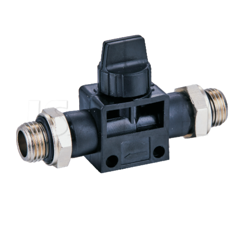
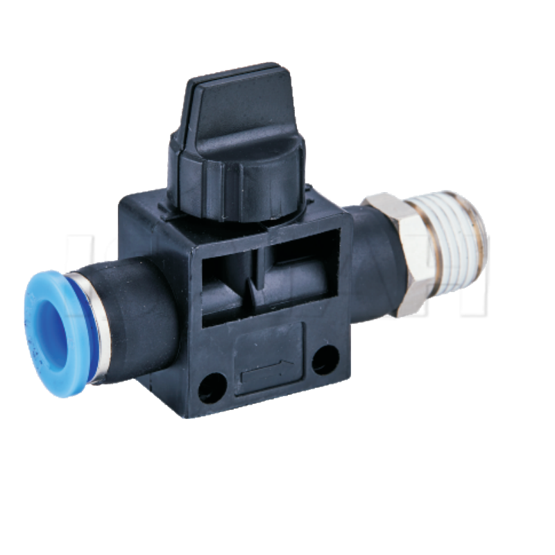
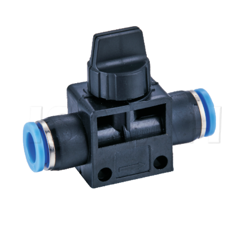
Automated directional control valves routinely manage the primary cycles of modern machinery. However, hand valves remain the critical fail-safe for maintenance, isolation, and localized control in any pneumatic system. They serve as the physical barrier between active energy and vulnerable operators. Selecting the wrong manual valve actively compromises worker safety. It also delays routine maintenance operations and risks unplanned pressure drops across your facility. Facilities simply cannot afford accidental energy releases or starved actuators during critical tasks. This guide thoroughly breaks down how to evaluate, size, and implement these essential components. You will learn actionable strategies to ensure operational reliability while maintaining strict regulatory safety compliance. We explore core configurations, evaluation criteria, and practical installation steps to protect your teams.
Key Takeaways
Safety First: 3-way manual valves are strictly required for Lockout/Tagout (LOTO) procedures to exhaust residual downstream air.
Precision Sizing: Selecting the correct flow coefficient (Cv) prevents systemic pressure drops and actuator starvation.
Application Matching: Lever, push-pull, and rotary actuations must be matched to operator ergonomics and space constraints.
Strategic Placement: Proper installation locations (e.g., upstream of FRL units or at zone boundaries) dictate the effectiveness of the isolation strategy.
The Operational Role of Manual Air Control Valves
Unplanned downtime costs facilities thousands of dollars per hour. Hazardous energy releases during maintenance pose severe safety risks. Proper manual isolation serves as the foundational defense against these threats. You need robust mechanical boundaries to protect equipment and personnel. High-quality manual air control valves solve these problems by providing immediate physical intervention points.
Implementing these valves successfully requires meeting specific criteria. First, you must achieve reliable, zero-leak shutoff capabilities. A passing seal renders the isolation useless. Second, operators need a clear visual indication of the valve state. They must know instantly if the valve is open or closed. Third, the system requires immediate pressure relief for downstream pneumatic circuits. Trapped air causes unpredictable cylinder movements.
System integration demands a strategic approach. We must differentiate between zone isolation and global machine isolation. Global isolation shuts down the entire main air supply. It secures the whole machine for major overhauls. Zone isolation shuts down a specific sub-circuit. This allows operators to service a single actuator while the rest of the machine runs. Mixing these strategies creates operational bottlenecks. You must map your pneumatic circuits to determine where local control benefits productivity.
Core Configurations and Functional Mechanisms
Understanding valve configurations is essential for safe system design. Different mechanisms serve entirely different operational purposes. You cannot substitute them interchangeably.
2/2-Way Valves (On/Off Isolation)
The 2/2-way valve offers basic on/off functionality. It has two ports and two positions. We primarily use them for basic air supply restriction. They work well when downstream exhaust is not required. You might also use them if another component handles the exhaust function separately. However, they carry significant limitations. A 2/2-way valve traps compressed air downstream after closing. It stops new air from entering but does not bleed existing pressure. Therefore, they are entirely unsuitable for safety-critical maintenance boundaries.
3/2-Way Valves (Shut-Off with Exhaust)
The 3/2-way valve stands as the industry standard for safety isolation. It has three ports and two positions. Moving the actuator to the closed position blocks the main supply air. Simultaneously, it connects the downstream circuit to an exhaust port. This vents downstream pressure directly to the atmosphere. It removes all potential pneumatic energy from the isolated zone. This mechanical action makes the machine safe to service.
4/3-Way and 5/3-Way Manual Valves (Directional Control)
Complex applications require 4/3-way or 5/3-way valves. These provide manual directional control for pneumatic cylinders or motors. They commonly control clamping, pressing, or lifting mechanisms. The three positions allow for forward, reverse, and a neutral center state.
The center position configuration defines how the actuator behaves when idle:
Exhaust Center: Both cylinder ports vent to the atmosphere. The cylinder rod moves freely.
Closed Center: All ports are blocked. The cylinder holds its position securely.
Pressure Center: Both cylinder ports receive supply pressure. This equalizes force on equal-area cylinders.
Valve Configuration Comparison Chart
Configuration | Primary Function | Exhausts Downstream Air? | Ideal Application |
2/2-Way | Basic On/Off | No | Simple flow restriction |
3/2-Way | Isolation & Dump | Yes | Safety boundaries and LOTO |
4/3 & 5/3-Way | Directional Control | Depends on Center | Manual cylinder operation |
Evaluation Criteria: Selecting the Right Pneumatic Hand Valves
Selecting pneumatic hand valves requires evaluating multiple technical variables. You must size them correctly, choose appropriate actuation styles, and specify durable materials.
Sizing and Flow Coefficient (Cv)
Proper sizing prevents performance bottlenecks. You must match the valve port sizes to your existing airline dimensions. Common standards include NPT (National Pipe Taper) and BSPP (British Standard Pipe Parallel). Thread mismatches cause dangerous leaks. However, matching pipe diameter is only the first step.
You must evaluate the flow coefficient (Cv). The Cv rating indicates how much air volume passes through the valve. If you select a valve with a low Cv, you restrict downstream flow. This starves actuators and slows machine cycle times. You must calculate the acceptable pressure drop (ΔP) across the valve at your maximum required flow. A heavily restricted valve forces the compressor to work harder.
Actuation Style and Ergonomics
Operator interaction defines the actuation style. Ergonomics play a massive role in daily usability and safety response times.
Lever/Toggle: These provide the best visual state indication. You can see from a distance if the lever is up or down. They allow for quick, decisive state changes during emergencies.
Push-Pull: These valves suit compact panel mounting. The linear actuation saves space on crowded operator consoles. They are intuitive for simple on/off tasks.
Rotary: Rotary knobs allow for precise throttling. Operators prefer them for multi-position directional control. They prevent accidental bumps from shifting the valve state.
Material Selection and Environmental Scalability
Industrial environments destroy improper materials quickly. Standard manufacturing environments typically utilize aluminum or brass valve bodies. These metals balance cost, weight, and durability for clean indoor air.
Corrosive or washdown environments require extreme resilience. Food processing or chemical plants need 316 Stainless steel or specialized engineered plastics. These materials resist harsh cleaning agents.
Temperature ratings dictate your seal material evaluation. Most standard applications use Buna-N (Nitrile) seals. They perform exceptionally well in standard ambient temperatures. High-heat environments demand FKM or Viton seals. These compounds resist thermal degradation and aggressive synthetic compressor oils.
Seal Material Evaluation Table
Seal Material | Temperature Range | Best For | Limitations |
Buna-N (Nitrile) | −40°F to 212°F (−40°C to 100°C) | Standard factory air | Degrades in high heat |
FKM / Viton | −15°F to 400°F (−26°C to 204°C) | High heat and chemical exposure | Poor performance in extreme cold |
EPDM | −60°F to 300°F (−51°C to 149°C) | Outdoor weather exposure | Incompatible with petroleum oils |
Safety Imperatives: Lockout/Tagout (LOTO) Compliance
Machine safety is not optional. It is a strict legal requirement. Manual isolation valves form the backbone of your energy control program.
Regulatory Framework
You must navigate OSHA standard 29 CFR 1910.147 (Control of Hazardous Energy). This standard dictates how facilities handle pneumatic contexts. It requires you to isolate machines from their energy sources before servicing them. Relying on software stops or automated valves does not meet this standard. You need physical, manual intervention. The valve must physically sever the air supply and bleed downstream pressure.
Padlock Compatibility
A closed valve means nothing if someone can easily open it. You must evaluate valves for built-in lockout holes or locking clasps. A maintenance worker places their personal padlock directly through the valve mechanism. This physically prevents unauthorized repressurization. If the valve lacks integrated padlock holes, you must use bulky clamshell covers. Integrated locking mechanisms are far safer and easier to deploy.
Exhaust Capacity Risks
Many facilities overlook the exhaust port sizing. You must ensure the exhaust port capacity dumps system air rapidly. Undersized exhaust ports create deadly hazards. They leave dangerous residual pressure in the system during the initial maintenance window. A worker might assume the machine is safe because the valve is closed. However, an undersized port bleeds air slowly. The cylinder might still hold enough pressure to crush a hand minutes later. Always verify the exhaust Cv rating matches your safety timeline.
Tamper Resistance
Assess the physical durability of the lockout mechanism. Industrial environments experience heavy wear and tear. A flimsy locking clasp might snap if bumped by a forklift or heavy tool. The lockout feature must withstand significant physical force to maintain LOTO integrity.
Implementation Realities and Installation Best Practices
Purchasing the correct valve solves only half the problem. Proper installation dictates how well the valve protects your system.
Strategic Placement
Installation location is critical. You should install main isolation valves immediately upstream of Filter-Regulator-Lubricator (FRL) assemblies. Placing the valve here allows technicians to service the FRL units safely. They can change filter elements or refill lubricator bowls without depressurizing the entire plant loop.
Additionally, utilize zone valves. Place these closer to point-of-use actuators. Zone valves isolate specific machine sections. You prevent needing to vent the entire plant line for localized repairs. This saves massive amounts of compressed air and drastically reduces recovery time.
Orientation and Mounting
Pay close attention to valve orientation. You must ensure exhaust ports direct air safely away from operators. High-pressure exhaust blowouts can blind workers or blast debris into their faces.
You must fit exhaust ports with silencers. Venting compressed air generates severe decibel levels. Silencers manage this noise, keeping your facility compliant with OSHA hearing protection standards. They also catch particulate blowout, preventing oil mist from coating your floors.
Maintenance Assumptions
Manual valves require ongoing attention. Establish clear inspection intervals for seal degradation. Facilities often ignore manual valves until they fail. You must train personnel to recognize symptoms of internal bypassing. A constant hissing sound indicates a failing seal. Slow actuator drift when the valve is supposed to be closed signals dangerous internal leakage. Replace compromised valves immediately.
Conclusion
Securing your pneumatic systems requires diligent component selection. As we have explored, manual isolation goes far beyond simply stopping airflow.
Size strictly for flow: Match the Cv rating to your system demands to eliminate bottlenecks.
Configure for rapid exhaust: Always specify 3-way valves for isolation points to ensure dangerous downstream energy dissipates immediately.
Build for compliance: Insist on integrated padlock compatibility to enforce OSHA LOTO standards flawlessly.
Your next steps should begin with a thorough audit. Consult your facility's pneumatic schematics. Identify all current isolation points. Calculate the required Cv for any outdated components you find. Finally, partner with a reliable supplier to specify LOTO-compliant hardware that fits your operational ergonomics.
FAQ
Q: Can I use a standard 2-way ball valve for pneumatic lockout procedures?
A: No. A standard 2-way valve traps pressurized air downstream. Safety procedures require a 3-way valve that exhausts residual downstream energy.
Q: How do I determine the correct port size for hand valves?
A: Port size should match your pipe diameter, but the primary metric is the Cv value required by the system's total air consumption to avoid starving downstream components.
Q: Do manual air control valves require lubrication?
A: Most modern valves are pre-lubricated or utilize self-lubricating seals. However, installing them downstream of a lubricator necessitates continuous lubrication, as the initial oil washes away factory grease.
Q: What is the purpose of a silencer on a 3/2 hand valve?
A: When the valve is closed and downstream air vents to the atmosphere, a silencer reduces the sudden, potentially damaging high-decibel noise and disperses exhausted contaminants safely.