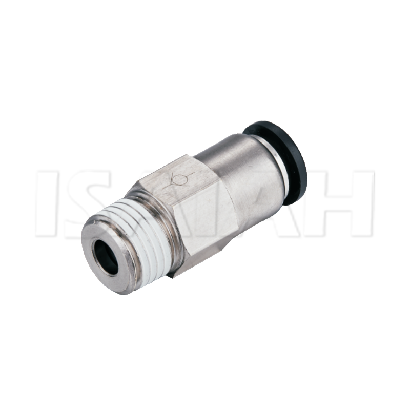
Did you know reverse airflow can destroy expensive pneumatic systems? Backflow causes catastrophic failures and costly downtime on the factory floor. In these high-stakes environments, a reliable check valve acts as the ultimate directional control safeguard. I have seen entire production lines halt simply because a sub-standard valve failed to hold pressure. This guide dives deep into the technical nuances of selecting the perfect one-way components. We cover everything from cracking pressure dynamics to sourcing from top-tier suppliers, ensuring your specific automation needs are met with absolute precision.
Key Takeaways
Directional Control: These are critical components that allow compressed air to flow in a single direction while completely blocking any reverse flow.
Cracking Pressure Matters: Selecting a unit with the precise minimum pressure required to open is essential for maintaining system efficiency and avoiding flow restrictions.
Material Compatibility: Standard industry materials like brass, nickel-plated brass, and engineered plastics offer specific advantages regarding durability, weight, and corrosion resistance.
Size and Space Constraints: Modern pneumatic designs rely on miniaturized innovations and specialized thread configurations to solve complex spatial limitations.
Supplier Reliability: Sourcing components from reputable manufacturers guarantees compliance with strict industry standards, ensuring long-term operational stability.
Navigating Current Trends in Fluid Power
Recent market analyses highlight a massive shift toward energy efficiency and miniaturization in fluid power circuits. Facility managers are scrutinizing compressed air leaks more intensely than ever before due to skyrocketing energy costs. The industry trend heavily favors ultra-low cracking pressure components and compact, high-flow designs. Engineers actively move away from bulky legacy fittings. They opt instead for integrated, lightweight solutions that reduce the overall footprint of automation cells while maximizing cycle speeds. Furthermore, the push towards smart manufacturing requires pneumatic systems to be highly predictable. Consistent cracking pressure is no longer just a nice feature; it is a strict requirement for synchronized robotic operations.
What is a Check Valve in a Pneumatic System?
A pneumatic one-way valve is a specialized two-port directional control component designed specifically for compressed air systems. Unlike complex multi-way manifolds that route air to various actuators, this device serves a single, critical function. It acts as a unidirectional flow path for compressed air.
Its primary purpose is to permit air media to flow freely in the forward direction while automatically closing to prevent backflow when upstream pressure drops. This automatic actuation requires no external control or electrical signal. Consequently, it serves as an incredibly reliable safety and control mechanism for industrial machinery.
How Do Pneumatic Check Valves Work?
The Mechanics of One-Way Flow
The internal mechanics of these valves are relatively straightforward but require high-precision engineering. The most common design utilized in industrial air circuits is the spring-loaded poppet mechanism. In this configuration, a movable poppet is held against a valve seat by a calibrated spring. When the incoming air pressure exceeds the tension of the spring, the poppet is pushed off the seat, allowing air to flow through the body. If the airflow stops or reverses, the spring forces the poppet back onto the seat, creating an airtight seal. Other variations include diaphragm designs, which use a flexible rubber element instead of a spring, though these are typically reserved for lower-pressure applications.
Understanding Cracking Pressure
When engineers specify components, cracking pressure is a non-negotiable metric. It is defined as the exact minimum upstream pressure required to overcome the internal spring force and begin opening the valve. If a pneumatic circuit operates at low pressures, selecting a unit with a high cracking pressure effectively blocks the entire circuit. Matching this metric to the specific operational baseline is vital. For instance, high-quality industrial models typically feature a precise cracking pressure of 0.1 MPa, ensuring they open reliably without restricting low-pressure automation sequences.
Flow Capacity and Pressure Drop
Every component added to a pneumatic circuit introduces resistance. A pressure drop occurs as compressed air forces its way past the internal spring. Engineers evaluate this using the flow coefficient, which measures the volume of air that can pass through the unit at a specific pressure drop. Failing to account for this pressure drop leads to underperforming actuators, sluggish cylinder actuation times, and an overworked air compressor attempting to compensate for the lost pressure.
Key Factors to Consider When Choosing Check Valves
Operating Pressure and Temperature Range
The foundational step in selecting any pneumatic component is aligning the product specifications with the system maximum operating parameters. A standard industrial air circuit typically operates between 80 to 120 PSI. The chosen component should ideally be rated for a maximum operating pressure of at least 1.0 MPa, or roughly 150 PSI, to handle unexpected pressure spikes safely.
Temperature is equally critical. The ambient facility temperature and the compressed air temperature dictate the internal seals required. Standard Nitrile seals are highly effective for general use between zero and 60 degrees Celsius. If the circuit operates near heat-generating machinery, high-temperature Viton seals become mandatory to prevent the internal rubber from hardening and leaking.
Flow Rate Requirements
Sizing the unit correctly ensures it does not create an unintended bottleneck. The internal orifice size dictates its maximum flow rate. Procurement managers must verify that the rated flow capacity exceeds the maximum flow requirement of the downstream components. A restriction in flow will visibly reduce the overall cycles-per-minute of an automated machine.
Port Size and Connection Types
A directional control device is only useful if it can be securely integrated into the existing pneumatic infrastructure. Matching the port size and connection type to the existing tubing and manifolds is essential to prevent leaks. Engineers should carefully review standardized configurations to ensure seamless compatibility with their specific piping architecture.
Common Types of Check Valves for Air Systems
Standard Inline Check Valves
Standard inline designs are the workhorses of industrial pneumatics. They feature a straightforward, symmetrical body design with threaded ports on both ends, allowing them to be installed directly into a run of rigid piping or flexible tubing. Manufactured from robust metals, they are heavily favored for their high flow capacities and reliability in demanding manufacturing environments.
The Mini Check Valve
As industrial automation moves toward more compact footprints, the demand for miniaturized components has surged. A mini check valve operates on the exact same physical principles but features a significantly smaller housing. Think about a robotic arm on a high-speed assembly line. Minimizing the weight of end-of-arm tooling is critical to reducing inertia. These low-profile designs often utilize G-thread configurations with internal O-rings to save space and ensure a perfect seal without bulky tape.
PCVC Check Valve
The PCVC check valve represents a significant leap in installation efficiency. These components integrate standard backflow mechanics with push-to-connect fitting technology. Instead of wrestling with wrenches and messy thread sealants, technicians simply push the pneumatic tubing directly into the port. This creates an instant, airtight seal. It is highly advantageous in dynamic production environments where rapid maintenance is required.
Material Selection: Why Brass and Plastics Dominate
Brass and Nickel-Plated Brass
In the realm of pneumatic circuitry, brass is widely considered the industry standard for component bodies. It offers an optimal balance of high tensile strength and rust resistance. Brass easily withstands the intense pressures associated with heavy industrial compressors without fracturing.
Many premium units undergo a nickel-plating process to further enhance these properties. Nickel-plated brass provides superior surface hardness, significantly increasing wear resistance in high-vibration environments. More importantly, the nickel layer offers exceptional chemical resistance, protecting the brass underneath from harsh industrial cleaning agents.
Engineered Plastics and Composites
For applications where weight reduction is a primary objective, engineered plastics such as Polybutylene Terephthalate are heavily utilized. Plastic variants are highly favored in the packaging and semiconductor industries. Beyond being lightweight, plastics offer excellent resistance to specific corrosive chemicals that might otherwise degrade metal components.
Stainless Steel
While not as common as brass or plastic due to its higher cost, stainless steel is mandated in extreme environments. Pneumatic circuits operating in food and beverage processing or highly corrosive marine environments rely on stainless steel components to maintain strict sanitary standards.
Navigating Thread Standards in Pneumatic Circuits
Selecting the correct thread standard is a critical procurement step. A mismatch in thread types will result in stripped threads, severe air leaks, and potential safety hazards under pressure.
G-Thread vs NPT vs R-Thread
Global manufacturing relies on a few dominant thread standards. Understanding the difference is vital for sourcing the correct components.
Thread Standard
Description
Sealing Mechanism
Common Regional Usage
G-Thread
British Standard Pipe Parallel. The threads are straight and parallel.
Requires an O-ring or sealing washer compressed against a flat surface.
Europe, Asia, and globally in modern automation.
NPT
National Pipe Tapered. The threads taper down in diameter.
Thread deformation; requires Teflon tape or liquid sealant to fill the gaps.
North America.
R-Thread
British Standard Pipe Tapered. Tapered threads similar to NPT but with a different thread angle.
Thread deformation; requires sealant.
Asia and older European machinery.
G-threads have become increasingly popular in modern pneumatic components because they do not require messy thread sealants. They rely instead on a captive O-ring. This ensures a clean installation and prevents sealant debris from entering the sensitive pneumatic circuit.
Male vs Female Threads
Beyond the standard, buyers must specify the gender orientation of the installation point. Male threads feature threading on the outside of the fitting, designed to screw into a manifold or cylinder port. Female threads feature threading on the inside, designed to accept a male fitting or threaded pipe. Engineers must carefully map out the circuit to determine the exact configuration required at each junction.
How to Choose the Right Manufacturers
Sourcing components from reputable Check Valves Manufacturers is critical. The cost of component failure far exceeds the initial purchase price. Unplanned downtime, damaged actuators, and safety hazards are real risks when utilizing substandard parts. Therefore, evaluating your supply chain requires a systematic approach focused on quality assurance, product range, and reliable delivery.
Quality Assurance and Testing Protocols
The primary function of a backflow prevention device is absolute sealing capability. Leading manufacturers do not rely on random batch testing; they implement stringent end-of-line testing protocols. A reliable manufacturer will test for zero leakage using advanced pressure decay methods or precise bubble testing under water. Specifically, the cracking pressure must be highly consistent across thousands of units to ensure predictable circuit behavior.
Evaluation Metric
Standard Requirement
Why It Matters for Pneumatic Circuits
Leakage Testing
100 percent End-of-line testing
Prevents slow pressure drops in holding circuits, reducing compressor cycling and energy waste.
Material Traceability
ISO 9001 Certification and Material Test Reports
Ensures the brass or polymer used matches the technical data sheet, preventing premature corrosion.
Cracking Pressure Variance
Plus or minus 10 percent of stated specification
Guarantees that multiple valves in a parallel circuit will open simultaneously without causing flow imbalances.
Cycle Life Testing
Minimum 1 to 5 million cycles depending on design
Validates the fatigue resistance of internal springs and the wear resistance of soft seals.
Customization and Product Range
Industrial automation is rarely one-size-fits-all. A top-tier manufacturer will offer a comprehensive catalog that addresses standard, compact, and specialized pneumatic applications. Partnering with a supplier that provides a broad product range simplifies the procurement process and ensures compatibility across different sections of a machine.
Supply Chain Reliability and Technical Support
Supply chain consistency is just as important as the physical product. Manufacturers must demonstrate robust inventory management and predictable lead times. Delays in receiving a simple directional control device can stall the commissioning of a million-dollar automation cell. Strong technical support is a hallmark of a reliable manufacturer. Suppliers who transparently provide CAD models and direct access to application engineers should always be prioritized.
Common Mistakes to Avoid in Pneumatic Component Selection
Even with the best components from top-tier manufacturers, improper selection or installation can lead to catastrophic system failures. Engineers frequently encounter pneumatic circuit issues that trace back to fundamental errors in specification. Avoiding these common pitfalls ensures system longevity and operational safety.
Oversizing or Undersizing the Valve
One of the most frequent errors in pneumatic design is selecting a component based solely on the pipe or tubing size without calculating the actual flow rate requirements.
If a unit is too small for the required flow, it acts as a severe restriction in the circuit. This results in a high pressure drop. Consequently, downstream actuators will be starved of air. They will actuate slower than designed, directly impacting machine cycle times.
Conversely, oversizing can be equally detrimental. If the flow rate is too low for a large internal orifice, the air pressure may barely exceed the cracking pressure. This causes the internal poppet to hover near the seat, rapidly opening and closing. This phenomenon generates excessive noise and rapidly destroys the internal seals and springs due to high-frequency mechanical fatigue.
Ignoring Environmental and Media Factors
Standard pneumatic components are typically equipped with Nitrile seals and standard brass bodies, which are perfectly adequate for clean indoor environments. Applying these standard components in harsh environments is a recipe for failure. If the circuit is exposed to synthetic compressor oils, extreme ambient temperatures, or corrosive washdown chemicals, material selection must be upgraded immediately.
Installing the Valve Backwards
While it sounds elementary, installing a directional device backwards is the most common installation error on the factory floor. Because these units only allow flow in one direction, a backward installation immediately blocks the main air supply or traps exhaust air. If installed backward on a cylinder exhaust, the cylinder will extend but refuse to retract, effectively locking the machine.
Common Mistake
Immediate Symptom
Long-Term Consequence
Corrective Action
Undersizing
Slow cylinder actuation
Overworked compressor
Calculate required flow coefficient and resize.
Oversizing
Buzzing or rattling noise
Premature seal or spring failure
Match flow rate to valve capacity.
Wrong Materials
Leaks around the body
Complete loss of system pressure
Audit temperature and chemical exposure.
Backward Install
Zero downstream pressure
Potential pump or compressor damage
Verify physical flow arrow on body.
Conclusion
Choosing the right directional control components demands meticulous care. You must rigorously evaluate operating pressure, flow requirements, and environmental conditions to ensure optimal performance. Upgrading to robust materials like nickel-plated brass offers outstanding system durability, while selecting the correct thread type actively prevents hazardous leaks. Ultimately, the right valve protects your structural integrity and boosts operational efficiency significantly.
Ready to optimize your pneumatic circuits? Browse high-quality catalogs for reliable pneumatic components at Isaiahpc.com. Whether you need compact push-to-connect solutions or robust nickel-plated brass designs, our extensive product range ensures your specific automation needs are met. Contact our experienced engineering team today to select the exact specifications for your facility.
Frequently Asked Questions
What is the difference between a standard one-way valve and a pilot-operated version?
A standard directional valve operates purely automatically based on the pressure differential across its ports. It allows flow in one direction and mechanically blocks reverse flow. A pilot-operated version includes a third port for a pneumatic pilot signal. Under normal conditions, it acts just like a standard valve. When pressurized air is applied to the pilot port, it forces the internal mechanism open, allowing reverse flow. This is crucial in safety applications, such as holding a vertical load in place if main pressure is lost, but allowing the load to be lowered intentionally when commanded by the pilot signal.
Can I use a water valve for a pneumatic air circuit?
No, you should never substitute liquid valves for pneumatic applications. Air is a highly compressible gas with much smaller molecules than water, meaning it can escape through microscopic gaps that water cannot. Pneumatic valves are engineered with specific soft elastomeric seals and precision-machined seats designed specifically to prevent gas bypass. Liquid valves often rely on metal-to-metal seating or the fluid viscosity to create a seal, which will result in unacceptable air leakage, continuous compressor cycling, and energy waste in a pneumatic circuit.
How do I know if I need a miniaturized component?
You should specify a mini variant when dealing with strict spatial constraints or weight limitations. They are highly recommended for applications involving micro-pneumatic logic circuits, small bore cylinders, and compact control panels. In robotics and automated pick-and-place systems, minimizing the weight of end-of-arm tooling is critical to maintaining high speeds and reducing robot arm fatigue. A miniature valve provides the necessary directional control without adding unnecessary bulk or mass to the moving components.
What makes a push-to-connect directional valve different?
The defining feature of this specialized valve is its integration of push-to-connect fitting technology directly into the directional valve body. Traditional installations require a threaded body plus two separate threaded-to-tube fittings, requiring Teflon tape and wrench tightening. The push-to-connect design allows technicians to simply push the calibrated pneumatic tubing directly into the valve for an instant, secure, and leak-free connection. This significantly accelerates assembly times and eliminates the risk of thread sealant contaminating the internal pneumatic circuit.
How do I test a pneumatic one-way valve for internal leaks?
The most reliable field method involves a simple bubble test. Pressurize the downstream port while leaving the upstream port open to the atmosphere. Apply a specialized leak detection fluid over the open port. If bubbles form, the internal seal is compromised, and the unit requires immediate replacement.
What causes a pneumatic valve to chatter during operation?
Valve chatter typically occurs when the component is oversized for the actual flow rate. The air pressure barely exceeds the cracking pressure, causing the internal poppet to rapidly bounce against the seat. Resizing the component to match the precise flow requirements of your circuit will eliminate this destructive vibration and prevent premature mechanical failure.
Mainly produce the pneumatic components, pneumatic control components, pneumatic actuators, air condition units etc. The sales network are all over the provinces of China,
and more than 80 countries and regions in the world.