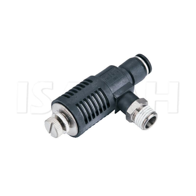
Are sluggish pneumatic cylinders dragging down your entire production line? Standard pneumatic setups often force exhaust air through long, convoluted valve channels. This creates a severe bottleneck of backpressure that bogs down your system. You might think the solution is a larger compressor or oversized actuators. In reality, the fix is much simpler and far more cost-effective. In this technical breakdown, you will discover exactly how localized venting resolves this friction issue, transforming slow actuators into highly efficient, high-speed performers.
Key Takeaways for System Optimization
Eliminates Backpressure: Venting air directly to the atmosphere near the cylinder completely bypasses long airlines and control valves that generate parasitic drag.
Dramatically Increases Speed: Removing exhaust resistance allows cylinder extension and retraction speeds to increase significantly. This directly improves machine cycle times.
Noise Management is Crucial: Rapidly exhausting pressurized air creates hazardous noise levels. Integrating proper silencing components protects worker hearing and maintains OSHA compliance.
Precision is Possible: Specialized control components allow engineers to fine-tune exact actuation speeds while still benefiting from localized air dumping.
Quality Matters: Utilizing high-grade components and properly matched connections ensures system longevity, prevents costly air leaks, and sustains peak operational performance.
Understanding the Quick Exhaust Valve in Pneumatic Systems
In the realm of pneumatic automation, efficiency is dictated by a single metric. How rapidly can compressed air enter and exit an actuator? A quick exhaust valve is a specialized pneumatic component engineered to provide an immediate, unrestricted exhaust path for air leaving a cylinder. Rather than forcing the exhausting air to travel all the way back through the pneumatic circuitry to the main directional control valve, this component redirects it straight into the ambient atmosphere.
Specifically, this localized venting drastically reduces the volume of air that must traverse narrow tubing. Minimizing that fluid friction and aerodynamic resistance is the secret to high-speed actuation.
To truly grasp the value of this component, we must compare it against traditional setups. Typically, the directional control valve manages both the supply and the exhaust of compressed air. When a cylinder retracts, the air on the non-pressurized side of the piston must travel from the cylinder port, push through meters of polyurethane tubing, re-enter the control valve, and finally squeeze out through the exhaust port. This long journey acts like a traffic jam.
In contrast, installing a venting component directly on or immediately adjacent to the cylinder port changes the route entirely. When the directional control valve shifts to exhaust, the local valve senses the pressure drop and instantly opens a large port. The long tubing and the control valve are bypassed entirely. This allows the cylinder to move without hesitation.
Core Comparison: Standard vs. Optimized Exhaust
Performance Metric
Standard Valve Setup
Quick Exhaust Setup
Exhaust Path Length
Long — Travels back to main control valve
Extremely Short — Vents locally at the cylinder
Backpressure Level
High — Causes piston resistance
Virtually Zero — Unrestricted flow
Cylinder Speed
Sluggish — Limited by tubing diameter
Maximum — Limited only by mechanical load
Energy Efficiency
Low — Wastes energy fighting trapped air
High — Full supply pressure moves the load
Industry Perspectives: The Push for Pneumatic Efficiency
Looking at recent developments in industrial automation, particularly within e-commerce fulfillment, stamping presses, and high-speed packaging, there is a clear paradigm shift. Historically, engineers facing slow cycle times would simply oversize their pneumatic cylinders or crank up the mainline compressor pressure. Today, that brute-force approach is widely recognized as financially and environmentally unsustainable. Rising energy costs mean facilities can no longer afford to waste compressed air.
Furthermore, the current industry trend is hyper-focused on micro-optimizations. Engineers are extracting maximum speed and force out of existing, correctly sized actuators. By strategically deploying localized exhaust solutions, modern manufacturing plants are effectively slashing cycle times by crucial fractions of a second per stroke. Over an eight-hour shift, these milliseconds compound into massive production gains. Best of all, this is achieved without the massive energy penalty of upgrading to larger compressors.
The Mechanics of Maximizing Cylinder Velocity
To comprehend how cylinder speed is maximized, you must look at the physics of pneumatic actuation. A cylinder moves because compressed air pushes against the surface area of its internal piston. But for that piston to surge forward, the air occupying the space on the opposite side must be evacuated. If that evacuation path is narrow or long, the escaping air compresses against itself. This creates a resisting force known as backpressure.
Backpressure acts as a pneumatic brake. By virtually eliminating this resistance, a localized venting valve ensures that the supply pressure is entirely dedicated to moving the load rather than fighting trapped air.
The internal mechanics of these valves are elegantly simple. They typically rely on a flexible lip seal, a diaphragm, or a shuttle mechanism that reacts instantaneously to pressure differentials. During the inlet phase, compressed air travels from the directional control valve into the local unit. The incoming pressure forces the internal seal against the exhaust port, sealing it shut. The air is then directed into the cylinder, actuating the piston.
Consequently, when the directional control valve shifts to the exhaust phase, it cuts off the supply pressure. This sudden pressure drop causes the internal seal to snap backward. This rapid movement simultaneously closes off the inlet port and throws open the exhaust port. The pressurized air inside the cylinder is given a wide, unobstructed path to vent.
Balancing Speed and Safety: Managing Acoustic Hazards
While maximizing speed is the goal, the rapid evacuation of compressed air introduces a severe environmental hazard. When highly pressurized air is suddenly dumped into the ambient atmosphere, the rapid expansion of gas creates a localized shockwave. On the factory floor, this is perceived as a loud, piercing hiss or a sharp pop.
In a facility with dozens of actuating cylinders, this continuous noise easily exceeds permissible exposure limits. Prolonged exposure to unprotected pneumatic exhaust noise, which frequently climbs past 90 decibels, can lead to permanent hearing damage for operators.
To mitigate this acoustic hazard without sacrificing system speed, engineers must utilize an exhaust valve with silencer. This setup integrates a noise-dampening component directly into the exhaust port. It allows the air to vent locally while effectively managing the acoustic energy. For instance, components operating at standard industrial pressures between 0.1 and 1.0 MPa require robust silencing to maintain a safe working environment.
An Exhaust silencer operates on the principle of diffusion. Instead of allowing the air to exit through a single large orifice, it forces the blast through a highly porous material like sintered brass. This breaks up the turbulent sound waves and slows the air expansion just enough to drastically lower the decibel level. When properly sized, a high-quality silencer achieves this acoustic dampening while causing negligible backpressure.
Achieving Precision: Controlling the Stroke
Eliminating backpressure is highly desirable, but absolute maximum speed is not always the best outcome. If a pneumatic cylinder actuates too violently, it generates massive kinetic energy. This causes severe mechanical shock at the end of its stroke. Uncontrolled impact can damage delicate tooling, fatigue internal seals, or destroy fragile products on the assembly line.
In these scenarios, you need a way to harness rapid exhaust capabilities while maintaining strict control over piston velocity. The solution to this engineering challenge is the speed control exhaust valve. This specialized component merges the rapid, localized dumping action of a standard valve with the precise flow regulation of a needle valve.
It provides operators with the ultimate middle ground. The exhaust air still dumps locally at the cylinder port, completely avoiding the friction of remote control lines. However, before the air hits the atmosphere, it must pass through an adjustable orifice controlled by a finely threaded dial. By turning this dial, technicians can meter exactly how fast the air escapes. Available in standard port sizes from G1/8 to G1/2, these units provide total control over the cylinder stroke speed, ensuring smooth and repeatable actuation.
Essential Connections: Component Matching
A high-speed pneumatic circuit operates as a cohesive unit. Its overall efficiency is strictly limited by its most restrictive component. Upgrading your valves is a wasted investment if the connections bridging them to the cylinder are undersized or poorly designed. Improper connections act as throttles, accidentally recreating the very backpressure you are trying to eliminate.
Securely connecting these components requires precision-engineered Exhaust Fittings designed specifically for high-flow applications. When selecting your connections, thread standards and material composition are paramount. Mixing thread types will result in thread galling and inevitable pressure leaks.
Common configurations include tapered threads which rely on interference fits and sealants, and parallel G-threads which utilize an O-ring for a cleaner seal. Regardless of the material, ensure the internal diameter of the fitting is large enough to handle the sudden volumetric flow rate of the exhausting air.
Installation Best Practices for Maximum Velocity
The golden rule of installation is proximity. The valve must be mounted as close to the cylinder exhaust port as physically possible. The objective is to minimize the dead volume of trapped air between the piston and the valve. If installed a meter away, the air within that tubing must still be pushed out before the valve can vent it. Threading the unit directly into the cylinder port ensures the pressure drop is sensed instantaneously.
Even premium pneumatic components require periodic inspection. To keep your cylinders operating at peak velocity, implement a proactive maintenance routine. First, inspect the internal seals. Over time, friction and synthetic compressor oils can degrade the internal diaphragm. If air leaks continuously from the exhaust port during the inlet phase, the seal is failing.
Second, monitor the silencer. Because they are porous, they act as unintentional filters, trapping ambient dust and aerosolized oil. A clogged silencer creates severe backpressure. Replacing it is often the quickest fix for a sluggish cylinder. Finally, routinely check threaded joints with a leak-detector solution, as high-vibration environments can loosen fittings over time.
Actionable Steps for Upgrading Your System
Optimizing pneumatic cylinder speed fundamentally comes down to one core principle. You must eliminate exhaust backpressure. Standard control valves and long tubing runs inherently restrict airflow, acting as a bottleneck that hampers facility productivity. Localized venting provides an elegant, cost-effective mechanical solution.
Raw speed must be balanced with operational safety and mechanical precision. By integrating proper silencing components, you protect worker hearing and maintain environmental compliance. Utilizing speed control variants ensures rapid actuation does not result in damaging mechanical shock. For facilities ready to eliminate pneumatic bottlenecks, upgrading to premium, well-matched ISAIAH components is the most logical step toward maximizing production efficiency. Visit the ISAIAH product catalog to select the exact thread sizes and flow capacities required for your specific actuators.
Frequently Asked Questions
Can I use a quick exhaust valve on both ends of a double-acting cylinder?
Yes. Installing these valves on both the extension and retraction ports of a double-acting cylinder will maximize actuation speed in both directions. This configuration is highly recommended for applications requiring rapid, symmetrical cycle times, such as high-speed sorting mechanisms or packaging machinery.
Where is the best place to install a quick exhaust valve?
For maximum efficiency, the valve must be threaded directly into the cylinder port. Any length of tubing placed between the cylinder and the valve creates dead volume. This trapped air will cause a slight delay in actuation and introduce unnecessary backpressure, defeating the purpose of the component.
Does a silencer slow down the cylinder?
A properly sized and newly installed silencer will cause minimal flow restriction and will not noticeably slow down the cylinder. However, because the porous material traps airborne contaminants and compressor lubricants, it can become clogged over time. A severely clogged unit will generate backpressure and reduce cylinder speed, making regular inspection necessary.
Can a quick exhaust valve reduce compressed air consumption?
While their primary function is speed, they indirectly aid in energy efficiency. By removing backpressure, the cylinder does not have to fight trapped air to move its load. This means you can often lower the main system regulator pressure while achieving the same mechanical force, ultimately saving compressed air and reducing compressor load.
What is the difference between a standard flow control valve and a speed control exhaust valve?
A standard flow control valve is typically installed further upstream near the manifold. It restricts the air traveling through the entire length of the pneumatic line. A speed control exhaust valve is mounted directly on the cylinder port. It dumps the exhaust air locally to eliminate airline friction, while its integrated needle valve allows the operator to precisely dial in the exact exhaust rate at the point of exit.
How do I know which valve size to buy?
Valve sizing must correlate directly with your existing pneumatic infrastructure. You should match the port size of the valve directly to the port size of your pneumatic cylinder, such as matching a quarter-inch NPT valve to a quarter-inch NPT cylinder port, to prevent bottlenecks. Additionally, ensure that the selected inlet connections match the outer diameter of your existing airline tubing.
Mainly produce the pneumatic components, pneumatic control components, pneumatic actuators, air condition units etc. The sales network are all over the provinces of China,
and more than 80 countries and regions in the world.